Summary: The ESD protection worked, and the device still failed the test. In one of our dual-brain designs, a Linux CPU set the mode of an MCU over three GPIO lines, and one mode used the code 111. During ESD testing the discharge never touched those lines directly, but it disturbed the whole device and could push all three lines high at the same time. The MCU read 111 and switched modes on its own. That is a change of operating state, so it fails performance criterion B. The fix was in firmware, not hardware: we moved that mode to a mixed code like 101. Here is why that works, why a design ends up with GPIO mode lines in the first place, and what to check in your own firmware.
What happened
The design had two brains: a CPU running Linux and an MCU next to it. The CPU told the MCU which mode to be in over three GPIO lines, MODE2, MODE1 and MODE0. The MCU read the three levels as a code and acted on it. In normal operation the lines carried a code such as 010 for one mode. Another mode used the code 111.
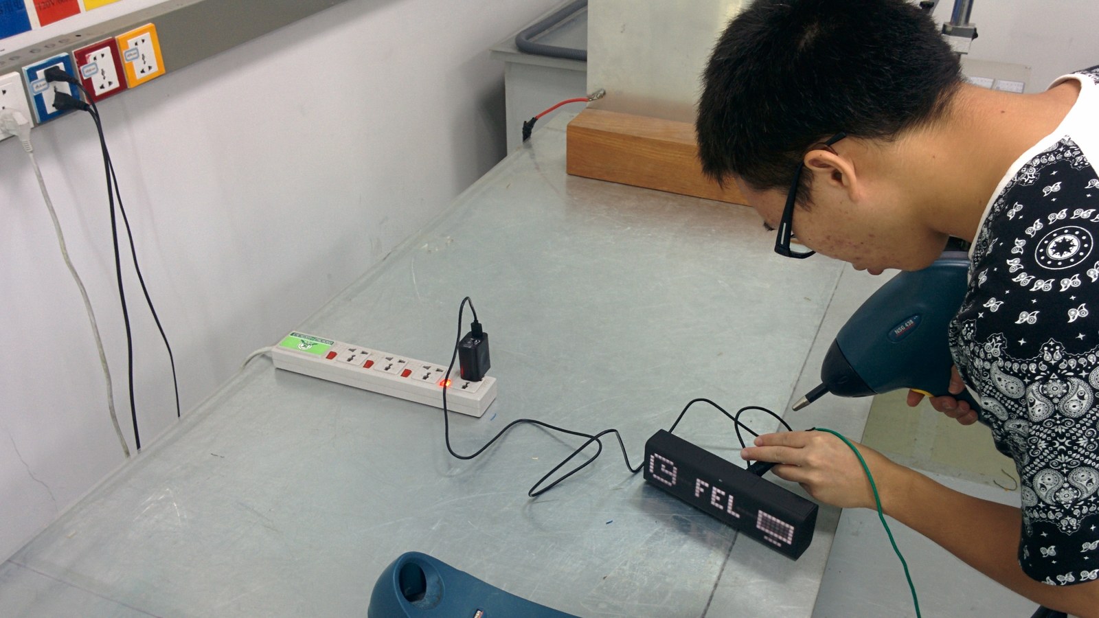
Then came ESD testing. The discharge didn’t hit those three lines directly. It affected the whole device, and that could push all three lines high at the same time. When that happened, the MCU read 111, which was a perfectly valid code, and switched modes on its own. When the disturbance was over, the lines went back to their real value, but the MCU was already in the other mode and stayed there.
Nothing was damaged. The protection did its job: no part burned, nothing latched up. The device simply did something nobody asked it to do.

Why that fails the test
IEC 61000-4-2 defines how to run the ESD test: where to apply the discharges, at which levels and how many. It does not decide what counts as a pass. That is the job of the product standard, through performance criteria.
For ESD, the product standard usually asks for criterion B. The device may glitch during the discharge, but it must keep operating as intended, without a change of operating state. Switching modes on its own is exactly that change. It doesn’t matter that every part survived and that the lines recovered a moment later. The device ended up in a state it was not supposed to be in, and it got there without anyone asking.
This is what makes the failure frustrating. The schematic is fine, the protection is in place and the board looks healthy. The weak point is the meaning the firmware gives to a pattern on three pins.
The fix: a mixed code
The fix was in firmware, not hardware. We moved that mode from 111 to a mixed code like 101.
A disturbance across the whole device tends to push every line in the same direction. All-high and all-low, 111 and 000, are exactly the patterns it creates. A mixed code like 101 needs one line to go the other way, so it is much less likely to appear from a disturbance that moves every line together. With the mode on 101, the all-high pattern no longer means anything, and the MCU can treat it as invalid and ignore it.
It doesn’t rule out ESD errors completely. A mixed code makes the dangerous pattern far less likely; it does not make it impossible. So the firmware still needs error detection and handling to block unintended mode changes. The new code is the first line of defence, not the only one.
Why GPIO and not a standard bus like I2C, UART or SPI?
A fair question. Sometimes a few GPIO lines are the only practical option:
- The mode is set from U-Boot, before the drivers are ready.
- There is no free bus left between the two chips.
- The MCU must react even if the CPU hangs.
And a bus isn’t immune either. I2C, UART or SPI can be hit by ESD too, so they also need error detection. The choice is not between a fragile interface and a safe one. It is about where the checking happens and how much of it the system can afford.
| Interface | When it fits | What it needs against ESD |
|---|---|---|
| A few GPIO lines | Mode set from U-Boot before drivers are ready, no free bus, or the MCU must react even if the CPU hangs | No meaningful action on 000 or 111, a stable level across several reads, a way back to normal operation |
| I2C, UART or SPI with a protocol | When the MCU’s resources and system constraints allow it | Explicit error detection (CRC or checksum), command validation and acknowledgment |
What to check in firmware
Whether your design uses GPIO lines or a bus, the same four checks apply to every input that can change what the device is doing:
- Prefer a protocol with explicit error detection. A CRC or checksum, command validation and acknowledgment, if the MCU’s resources and system constraints allow it. Standard buses like I2C, UART or SPI can carry such a protocol.
- If you do use GPIO lines, don’t assign a meaningful action to 000 or 111. Those are the codes a disturbance across the whole device produces. Use mixed codes for real modes and treat the all-high and all-low patterns as invalid.
- Before acting on a critical input, confirm it. Look for a stable level across several reads. A real command is still there on the next read; a disturbance usually is not.
- Give the device a way back to normal operation on its own if it still lands in the wrong state. Criterion B is about operating as intended without a change of state; a device that recovers by itself is far closer to that than one that waits for a person.
None of these needs a new part on the board. They change what the firmware is willing to believe.

Hardware and firmware at the same table
The protection protects the pins. The firmware decides what a pattern on those pins means. When the two are designed apart and only meet in the test lab, each side can be right on its own and the product can still fail.
The cheapest moment to catch this is before the first pre-scan. List every input and interface that can change the device’s operating state, including the quiet ones between two chips on the same board, and ask one question for each: could a disturbance that pushes every line the same way produce a valid command here?
How we help
At Smart Atoms we design the electronics and the firmware together, so the board and the code pass the same test. That includes the interfaces between CPUs and MCUs in dual-brain designs, ESD and EMC pre-compliance, and the firmware rules that keep a device in its intended state. See how we approach MCU firmware development. If your device has passed ESD without damage and still failed the test, talk to an engineer.
Source: Smart Atoms, from ESD testing of a dual-brain design (Linux CPU and MCU); IEC 61000-4-2 and product-standard performance criteria.